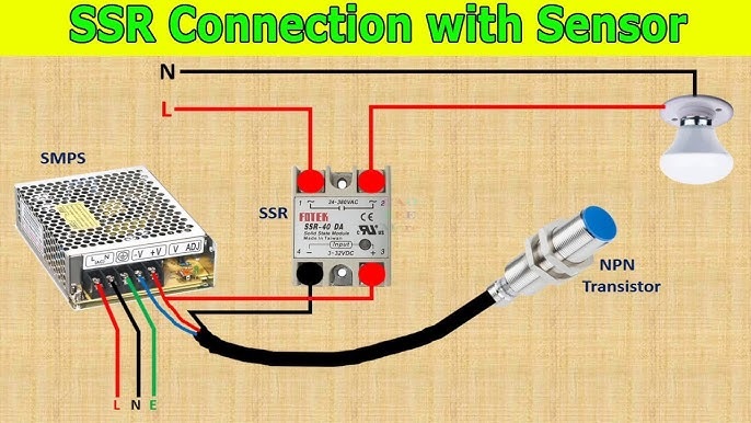
A solid state relay (SSR) wiring diagram is an essential tool for technicians aiming to design highly reliable and efficient control panels. Understanding these diagrams not only simplifies the installation process but also enhances overall system performance. Leveraging a clear wiring reference enables precision, reduces errors, and promotes long-term reliability in electrical control systems.
Understanding the Role of SSR in Control Panels
Solid state relays are electronic switching devices that control high-power circuits with low-power signals. Unlike mechanical relays, SSRs have no moving parts, which results in:
- Longer lifespan – reduced wear and tear increases operational longevity.
- Faster switching – improves system response time and efficiency.
- Silent operation – ideal for noise-sensitive industrial environments.
By consulting a wiring diagram, technicians can ensure proper connections and avoid potential mistakes that may compromise panel reliability. Understanding solid state relay wiring diagram ensures reliable performance.
Advantages of Using SSR Wiring Diagrams
Technicians benefit from SSR wiring diagrams in several key ways:
- Error Reduction – Accurate diagrams guide proper connections, minimizing installation mistakes.
- Enhanced Safety – Correct wiring reduces the risk of electrical hazards and system malfunctions.
- Time Efficiency – Clear schematics speed up assembly, testing, and troubleshooting.
- Consistency – Standardized diagrams allow multiple technicians to work efficiently on the same system.
Key Components Highlighted in SSR Wiring Diagrams
A comprehensive SSR wiring diagram illustrates all necessary elements for proper control panel integration:
- Input Terminals – Where the control signal is applied.
- Output Terminals – Connected to the load or controlled device.
- Power Supply – Provides necessary voltage for relay operation.
- Protection Devices – Such as fuses or snubber circuits to prevent electrical damage.
Understanding the interplay of these components ensures seamless panel performance and reliable operation.
Best Practices for Technicians
To maximize the benefits of SSR wiring diagrams, technicians should follow these practices:
- Double-check connections – Verify input and output terminals before powering the system.
- Follow voltage ratings – Ensure the SSR matches the load specifications.
- Use proper insulation – Protect wiring from short circuits and environmental hazards.
- Document changes – Keep diagrams updated for maintenance and future upgrades.
These practices, when combined with a detailed wiring diagram, contribute to a control panel that is both robust and efficient.
Conclusion
A solid state relay wiring diagram is more than just a schematic it is a blueprint for reliable and precise control panel design. By using these diagrams, technicians can enhance safety, reduce errors, and streamline the assembly process. The clarity and guidance provided by SSR wiring diagrams ultimately result in control panels that perform consistently and efficiently, making them an indispensable resource in modern electrical systems.